Signal Amplification and Noise Reduction in Electrophysiology Data

Written By: Craig Bradley
Oct 15, 2025
GEMINI (2025)
In the field of electrophysiology, the precision of measurements often dictates the quality and validity of scientific conclusions. The fundamental challenge inherent in recording neural or cardiac activity involves detecting minuscule biological potentials against a background of pervasive electrical interference. Achieving accurate, publication-quality data requires a robust methodology encompassing precise signal amplification and stringent protocols for effective noise reduction. The methodologies detailed herein represent essential practices for maximizing the signal-to-noise ratio (SNR) across various electrophysiological recording setups, from patch clamp to in vivo recordings. The consistent implementation of these principles ensures that the recorded biological events are accurately represented, free from contamination by environmental or instrumental artifacts.
Mastering Differential Amplification for Maximum Signal Fidelity
Effective signal amplification is the necessary first step in processing electrophysiology data, converting picoscale- or microscale-voltages into a usable range for digital conversion. Specialized instrumentation amplifiers are critical, as they are designed not merely to increase signal magnitude but, more importantly, to improve the signal-to-noise ratio early in the acquisition chain. The technique of differential amplification is central to this process.
In a differential amplifier configuration, the input stage measures the voltage difference between two points: the active electrode (measuring the biological signal) and a reference electrode (ideally placed near the signal source but not capturing the active signal itself). The amplifier then subtracts the common-mode voltage—which primarily consists of environmental electrical interference—from the signal.
The efficacy of this strategy is quantified by the Common-Mode Rejection Ratio (CMRR). A high CMRR indicates that the amplifier is highly effective at rejecting noise that is common to both input lines, such as 60-Hz line noise or radio frequency interference (RFI). For high-quality electrophysiology, specialized bioamplifiers are typically designed with CMRR values exceeding 100 dB, which is essential for maximizing the true biological signal while contributing to overall noise reduction.
Key factors in optimizing the amplification stage:
Gain Setting: The gain must be set appropriately to ensure the output voltage spans the full range of the Analog-to-Digital Converter (ADC) without causing saturation (clipping). Saturation occurs when the amplified signal exceeds the ADC’s maximum input voltage, leading to irreversible loss of high-amplitude signal features. Conversely, insufficient gain leaves the signal vulnerable to digitization noise. Proper gain ensures optimal utilization of the ADC's dynamic range.
Bandwidth: The amplifier's bandwidth defines the range of frequencies it processes. Setting the bandwidth too wide introduces high-frequency noise that is extraneous to the biological signal. Setting it too narrow, however, causes signal distortion by attenuating relevant, high-frequency components (e.g., action potential spikes). The low-pass filter (high-frequency cutoff) should be set just above the fastest frequency component of interest.
Input Impedance: The amplifier must possess an extremely high input impedance—typically measured in Gigaohms (
GΩ )—to prevent current flow away from the recording electrode. This minimizes loading effects, ensuring that the voltage measured at the input is a faithful representation of the true biological potential, which is critical for accurate signal amplification.
Eliminating Environmental Artifacts Through Hardware Noise Reduction
Environmental electrical interference is the most pervasive source of artifacts in electrophysiology, fundamentally limiting the effectiveness of signal amplification. Strict adherence to hardware-based noise reduction protocols is necessary to achieve a clean baseline recording.
Grounding and Shielding Protocols
The foundational hardware strategy involves establishing a proper grounding scheme and employing effective shielding:
Component | Purpose & Technique | Noise Reduction Benefit |
|---|---|---|
Grounding | Single-Point Grounding Scheme: All components (amplifier, digitizer, Faraday cage, table) are connected to a single common earth ground point, often through a medical-grade isolation transformer. | Prevents ground loops, which are a major source of 60-Hz/50-Hz line noise (mains hum). |
Shielding | Faraday Cage: A conductive enclosure (mesh or solid metal) surrounding the preparation and the head stage. The cage must be connected only to the single earth ground reference point. | Attenuates high-frequency electromagnetic interference (EMI) and RFI, including ambient noise reduction from cell phones and radio broadcasts. |
Cable Management | Use of shielded, twisted-pair cables for all low-voltage signal transmission. Avoid unnecessary cable length and parallel routing of power and signal lines. | Minimizes inductive and capacitive coupling between power lines and sensitive signal cables, reducing crosstalk and induced noise. |
Electrode and Headstage Considerations
The electrode and the headstage (the first amplification stage, typically mounted near the preparation) are highly sensitive to noise. The interface between the electrode and the preparation (e.g., the cell membrane or tissue) contributes junction potential and thermal noise. Using high-quality electrodes with low impedance and proper chloriding is essential.
The headstage's role is particularly critical. As the first stage of signal amplification, it must convert the high-impedance signal from the electrode into a low-impedance signal suitable for transmission to the main amplifier. Placing the headstage as close as possible to the preparation minimizes the length of the high-impedance signal path, which is most susceptible to capacitive coupling of ambient electrical noise. Careful maintenance of the headstage, ensuring clean connections and minimal moisture, contributes significantly to overall noise reduction.
Digital Signal Processing for Refined Data Quality
Even with meticulous hardware protocols, some irreducible noise components persist. These artifacts require software-based, or digital, noise reduction techniques applied post-acquisition. Digital filtering is a critical component of this process, but it must be applied judiciously to avoid altering the underlying biological signal.
Digital Filtering Strategies
The application of digital filters targets specific frequency components of the noise:
Notch Filter:
Purpose: To precisely remove the dominant mains interference (60 Hz in North America, 50 Hz elsewhere) and its harmonics.
Caution: Because the notch filter is very narrow, it can introduce transient ringing artifacts in the time-domain signal. Furthermore, if the biological signal contains relevant components precisely at 60 Hz (which is rare), these are irreversibly lost. The use of a sharp digital notch filter is often a last resort, as effective hardware grounding is the preferred method for this type of noise.
Low-Pass Filtering (LPF):
Purpose: To attenuate high-frequency noise components, such as wideband thermal noise and instrumental high-frequency chatter. This complements the hardware low-pass filter in the amplifier.
Effect: Smooths the signal, which is appropriate if the biologically relevant features are known to be slow (e.g., slow membrane potential fluctuations).
Principle: Based on the Nyquist-Shannon sampling theorem, the biological signal contains information only up to half the sampling rate. LPF is applied to prevent aliasing, where high frequencies are incorrectly represented as lower frequencies.
High-Pass Filtering (HPF):
Purpose: To remove very slow, baseline drift components, often caused by electrode drift, temperature changes, or respiratory movement (in in vivo recordings).
Effect: Stabilizes the baseline, which is essential for accurate amplitude measurements of fast events like action potentials.
Caution: Overly aggressive HPF (setting the cutoff frequency too high) can distort or completely remove relevant slow biological signals, such as synaptic potentials or slow wave oscillations.
Signal Averaging and Deconvolution
Beyond simple frequency-domain filtering, advanced techniques are employed for specialized noise reduction and feature extraction:
Signal Averaging: This technique is highly effective for signals that are time-locked to a stimulus (e.g., Evoked Potentials). By repeatedly stimulating the preparation and averaging the recorded signals, the random, uncorrelated noise components tend to cancel each other out, while the time-locked evoked signal, which is constant across trials, is enhanced. This dramatically improves the effective signal amplification of very weak evoked responses. The SNR improves proportionally to the square root of the number of averaged trials.
Deconvolution: In voltage-clamp experiments, the measured current is distorted by the capacitance of the cell membrane. Deconvolution algorithms can be used to mathematically remove the effect of the electrode and cell capacitance, yielding a cleaner, faster representation of the true ionic current, effectively restoring the biological signal shape and contributing to the optimal clarity of the acquired signal.
Optimizing the Signal-to-Noise Ratio (SNR) for Reliable Data
The successful acquisition of electrophysiology data ultimately hinges on achieving a high SNR, which is the quantitative measure of the power of the desired signal relative to the power of the background noise. Optimizing the SNR involves a continuous feedback loop between meticulous preparation and appropriate instrumentation.
SNR improvement is not solely about increasing the gain of signal amplification; it is a balanced effort where minimizing noise power is equally, if not more, impactful. For every 3 dB of noise reduction achieved, the clarity of the signal is doubled.
Best practice dictates approaching SNR optimization in a prioritized sequence:
Preparation and Environment: Minimize intrinsic biological noise (e.g., electrode stability, cell health) and environmental noise (Faraday cage, grounding). This provides the lowest possible noise floor before electronic processing begins.
Instrumental Amplification: Apply differential amplification with the highest possible CMRR and an appropriate gain setting that utilizes the full dynamic range of the ADC without clipping.
Digital Processing: Utilize targeted digital filtering only after hardware techniques have been exhausted. Employ signal averaging where applicable to enhance weak evoked responses.
By prioritizing physical noise reduction at the source and combining it with precision signal amplification, laboratory professionals can produce electrophysiological datasets of the highest quality and scientific validity. The continuous calibration and vigilance against new noise sources are ongoing requirements for maintaining optimal performance in advanced electrophysiology laboratories.
Common Challenges and Troubleshooting Noise Reduction
Electrophysiology setups frequently face challenges related to noise sources that are not immediately obvious. Understanding the signature of common noise types is crucial for rapid and effective troubleshooting.
Noise Signature | Potential Source | Corrective Action for Noise Reduction |
|---|---|---|
Sharp 60/50 Hz Peaks | Ground loops, poor shielding of the Faraday cage, or unshielded power cables near the preparation. | Verify single-point grounding; check continuity of Faraday cage ground; move power supplies away from the preparation. |
High-Frequency Hash | Radiofrequency interference (RFI) from cell phones, wireless routers, or instrumental chatter. | Ensure the Faraday cage is fully sealed; use a wider-band low-pass filter on the amplifier or in digital processing. |
Slow, Baseline Drift | Thermal noise from amplifier warm-up, slow electrode-electrolyte shifts, or temperature variations in the chamber. | Allow equipment to warm up for at least 30 minutes; use a high-pass filter digitally; stabilize the temperature control system. |
Excessively Large Noise | A broken connection to the ground or reference electrode, or amplifier saturation (clipping). | Check all electrode and headstage connections; reduce the gain setting on the main amplifier. |
Addressing these issues systematically ensures that the benefits of precision signal amplification are fully realized, preventing noisy data from compromising experimental outcomes.
Maximizing Data Quality Through Combined Signal Processing
Achieving exemplary electrophysiology data relies on an integrated strategy where hardware solutions lay the foundation for noise reduction, and instrumental design provides stable, high-fidelity signal amplification. Every stage, from the electrode-cell interface to the final digital filter, contributes to the overall SNR. The ability to distinguish genuine biological activity from measurement artifacts is the hallmark of a skilled electrophysiologist, and this skill is built upon a deep understanding of these fundamental principles. Continuous maintenance of equipment, verification of grounding integrity, and careful setting of amplifier parameters are non-negotiable practices for maintaining peak data quality over the long term.
Electrophysiology Data: Frequently Asked Questions
What is the primary difference between instrumental and digital signal amplification?
Instrumental signal amplification uses analog hardware (the amplifier) to increase the voltage magnitude before digitization, which is essential to fill the ADC's dynamic range. Digital amplification, applied post-acquisition in software, merely scales the digital values and does not inherently improve the SNR.
Why is single-point grounding critical for noise reduction in electrophysiology?
Single-point grounding ensures all setup components share the exact same ground potential. This prevents current flow between different ground connections, which eliminates ground loops—the primary cause of pervasive 50 Hz or 60 Hz line noise.
When should a digital notch filter be used for noise reduction?
A digital notch filter should be reserved as a secondary strategy for noise reduction when 60 Hz or 50 Hz mains noise persists despite rigorous hardware-based grounding and shielding protocols. Overuse risks introducing artifacts and removing any potential biological signal at that frequency.
How does signal averaging improve the signal-to-noise ratio?
Signal averaging works by exploiting the fact that the evoked biological signal is constant and time-locked to the stimulus, while the noise is random and uncorrelated. Averaging
This article was created with the assistance of Generative AI and has undergone editorial review before publishing.
Jan 09, 2026
Product News
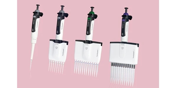
BRANDTECH Scientific Introduces the Transferpette® pro Micropipette: A New Twist on Comfort and Control
The latest addition to its trusted line of precision liquid handling instruments, engineered for comfort, control, and repeatable accuracy.
Jan 06, 2026
Featured, Technical Insight
New Research Frontiers Unlocked by Next-Generation Flow Cytometry
Next-generation flow cytometry systems using acoustic focusing are opening entirely new areas of research that were previously impractical or inaccessible with conventional flow cytometers.
Jan 05, 2026
Buying Guides
The Bottom Line: How Smart Microcentrifuge Tube Choices Impact Lab Efficiency and Cost
Innovative microcentrifuge tube solutions are more than just lab consumables—they’re strategic tools that can reduce costs, improve outcomes, and support long-term sustainability goals.
Jan 05, 2026
Buying Guides
Future-Proofing Your Lab with Innovative Microcentrifuge Tube Solutions
As laboratories evolve to meet the growing demands of modern science, even the most basic tools—like microcentrifuge tubes—are being reimagined.
Jan 05, 2026
Buying Guides
Microcentrifuge Tube Innovations: Driving Sustainable Change
Integrating next-generation consumables into standard workflows can lead to a more sustainable and responsible research environment.
Jan 05, 2026
Buying Guides
Single Use Plastics: How to Manage these Major Contributors to Lab Waste
Reducing lab waste isn’t just a sustainability issue—it’s a financial and operational one, too.
Jan 05, 2026
Buying Guides
Common Microcentrifuge Tube Challenges in Sensitive Molecular Workflows
Key factors that can impact the performance of microcentrifuge tubes for PCR, qPCR, and NGS and other sensitive applications
Jan 05, 2026
Buying Guides
How to Research the Right Microcentrifuge Tubes for Your Application
Selecting the right microcentrifuge tubes starts with understanding the specific demands of your application.
Jan 05, 2026
Technical Insight
The Best Confocal Microscopes of 2026
Discover the best confocal microscopes of 2026 for advanced imaging. Compare top models from Zeiss, Evident, and Nikon for speed, resolution, and budget.

Dec 24, 2025
Featured, Popular Products, Technical Insight
Emerging Mass Spectrometry Technologies to Improve Intraoperative Diagnostics
Advances in mass spectrometry may soon reshape surgery, improving diagnostic accuracy and impacting post-operative outcomes